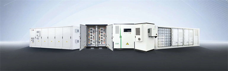
The lower battery case of the two models is made of die-cast aluminum alloy, and the upper case (cover plate) is made of stamped aluminum plate. Key Materials Used in Energy Storage. . The design process for battery cabinets involves: A recent Tesla Megapack installation in California used AI-driven simulation tools to optimize cell arrangement, reducing thermal hotspots by 40% compared to previous models. Now that's what I call a glow-up! Here's where engineers get feisty. Through the integration of advanced materials, fire-resistant designs, and regulatory. . What material is the energy storage cabinet made of? The energy storage cabinet is composed of a variety of materials that collectively foster efficiency, safety, and durability. The battery box is mainly composed of an upper cover and a lower case, which is the “skeleton” of the power battery module, and is used to protect the battery PACK against. . er torque to fasten DC power cable connections. The M6 cable bolts should be torqued to 70 in-lbs. The installation must follow all applica le national or local standards and regulations.
[PDF Version]
A crucial part of this installation process is understanding the wiring diagram for your photovoltaic (PV) solar panels. This diagram outlines the necessary connections between the panels, batteries, and other components to ensure a properly functioning system. . Compared to the schematic diagrams of most cutting-edge technological devices, solar panel wiring diagrams are actually remarkably simple. Schematics is one of the more technical parts of DIY solar, but it doesn't have to feel like. . A solar energy diagram is one of the most important tools in a PV project because it shows how the system is designed to work before the crew starts installing. Solar Panels perform at optimum capacity when placed in direct sunlight. When you install your Solar Power. . Have you decided to install your own photovoltaic system but don't know where to start? We have produced a number of connection diagrams for the various components of a solar photovoltaic system.
[PDF Version]
This guide breaks down how to read a PV system grounding diagram in under 10 minutes. Whether you're reviewing a plan set or prepping for an AHJ inspection, these tips will help you avoid costly mistakes. Mechanical connectors can be mounted to a module or racking frame with lay-in features which accept a copper wi e that bonds and grounds components, said Zwit. PV. . Photovoltaic panel ground wire fixing metho y must be bonded with the building equipment ground. Traditional: Daisy Chained Copper Wire between co ponents. What Is a PV System Grounding Diagram? A PV system grounding diagram is a dedicated part of. . Grounding a solar photovoltaic (PV) system involves establishing a low-resistance conductive pathway that connects the non-current-carrying metal components of the array to the earth. This pathway safely directs electrical current away from the equipment and structure in the event of an electrical. .
[PDF Version]
The wiring diagram for a PV combiner box outlines the connections and components needed to properly configure and install the box. These safety devices protect the solar panels from overcurrent and short circuits. The wiring diagram will indicate. . In our guide, we unpack how to wire solar panels and provide diagrams illustrating solar schematic examples for every solar setup, from residential to RV to camper van. You'll be ready to power up your home or get on the road in no time. Without it, wiring becomes tangled, voltage drops occur, maintenance costs rise, and safety risks increase. Most modern photovoltaic systems for residential or portable use don't actually require much “wiring. Credit to AK Electric Diy For a. .
[PDF Version]
To learn more about how wind turbines work, one can start by looking at the diagram above and study each component of a wind turbine. Step-by-step look at each piece of a wind turbine from diagram above:. Wind energy is the kinetic energy of the motion of a large mass of air on the surface of the Earth, which is produced by the non-uniform heat of the Earth's surface by the Sun. The air above the ground gets heated and expanded by the solar heat which is pushed upward by cool dense air causing the. . Wind turbines work on a simple principle: instead of using electricity to make wind—like a fan—wind turbines use wind to make electricity. A generator can take this mechanical energy and turn it into electricity for general consumption or for a specific purpose, like grinding grain or pumping water. Because it is generated by. .
[PDF Version]
Explore the structure and components of a solar panel diagram, understanding its key elements and how each part contributes to harnessing solar energy. . Solar panels are not a single functional element, but modules composed of multiple structural units. Each component plays a distinct role in optical protection, electrical energy conversion, mechanical support, and electrical connection. The most crucial component of the solar panels is the photovoltaic (PV) cells. . Solar panels use photovoltaic cells, or PV cells for short, made from silicon crystalline wafers similar to the wafers used to make computer processors. The silicon wafers can be either polycrystalline or monocrystalline and are produced using several different manufacturing methods. Working Principle: The working of solar cells involves light photons creating electron-hole pairs at the p-n. . What is the raw material that composes a photovoltaic module? Have you ever wondered what is the structure of a photovoltaic module and what are the main materials? There are many solutions available on the market and many raw materials that can be found, but the philosophy for manufacturing a. . A solar panel (also called a photovoltaic module) is the core unit that converts sunlight into usable electricity ⚡. Its design is like a carefully engineered “sandwich” structure 🥪, where multiple functional layers are laminated together. This ensures long-term durability and high efficiency even. .
[PDF Version]