Required grounding equipment includes copper-clad ground rods (5/8 inch or 3/4 inch diameter, 8-10 foot length), grounding clamps, UL2703 certified bonding products, and listed terminal bars. Ground rod spacing requires minimum 6 feet separation between electrodes. . Many modern grid-tied installations use ungrounded PV arrays paired with transformerless (non-isolated) inverters that establish a functional ground reference and rely on electronic ground-fault detection. Solidly grounded PV source circuits remain a permitted configuration and are still used in. . If separate grounding systems and grounding electrode conductors (GECs) are installed in a structure or different buildings, they should be combined at a common point (busbar or terminal) and connected to the common grounding electrode system. The main bonding jumper (MBJ) and grounding electrode. . Solar PV grounding systems require specific equipment to meet National Electrical Code (NEC) safety standards under sections 690. This simple yet critical detail can save you time, money, and headaches down the road. Whether you're a DIY enthusiast or just want to understand the process better, this. . The NEC is the primary guiding document for the safe designing and installation practices of solar PV systems in the residential and commercial markets in the United States.
[PDF Version]
Article 690 of the NEC mandates that #8 AWG or #6 AWG are the smallest wires that can be used with grid tied solar panels and inverter systems, and for solar panel output circuits, #10 or #12 AWG are allowed. A ground rod is also recommended if the installation area is. . Grounding is one of the most critical elements of any solar panel installation. In this guide, we'll walk you through the ins and outs of solar. . Grounding a solar photovoltaic (PV) system involves establishing a low-resistance conductive pathway that connects the non-current-carrying metal components of the array to the earth.
[PDF Version]
Article 690 of the NEC mandates that #8 AWG or #6 AWG are the smallest wires that can be used with grid tied solar panels and inverter systems, and for solar panel output circuits, #10 or #12 AWG are allowed. A ground rod is also recommended if the installation area is prone to. . Therefore, you must ground solar with the right wire sizes. This is because you will draw a maximum of 100 watts at 12 volts which results in 8. Figure 1: Example of a grounding arrangement on the AC side. (1) Positive. . The ground wiring, coming from the grounding screw on the outer shell of the inverter, was twisted into a coil and hung below the base of the inverter.
[PDF Version]
In this guide, we'll walk you through the ins and outs of solar panel grounding, covering everything from basic concepts to step-by-step instructions. The most important takeaway? Always use #6 AWG bare copper wire for outdoor grounding to meet National Electric Code requirements. . Properly grounding solar PV systems is one of the most critical aspects of a safe and reliable installation, governed by Part V of NEC Article 690. It is a mandatory practice required by NEC and IEC codes to protect both equipment and personnel from damage and electric shock hazards. This article covers grounding. . In solar PV systems, grounding ensures that all exposed conductive parts of electrical equipment are properly connected to the ground, while earthing ensures that any The two processes help mitigate the risk of Moreover, they assist in meeting regulatory standards for system safety and compliance. . Grounding and bonding are two distinct safety requirements for solar photovoltaic systems. Grounding connects electrical components to Earth at zero voltage potential. more Grounding your solar system is a crucial step in ensuring that your system operates safely and efficiently.
[PDF Version]
The NFPA and IEEE recommend a ground resistance value of 5 ohms or less while the NEC has stated to “Make sure that system impedance to ground is less than 5 ohms specified in NEC 50. In facilities with sensitive equipment it should be 5ohms or less”. Ideally, a ground should be zero ohms of resistance, but. . The grounding electrode system must achieve a maximum resistance of 10 ohms, though local regulations may specify stricter requirements. Installation of surge protection devices (SPDs) is mandatory to protect against lightning strikes and voltage surges. DISTRIBUTION LINE FAULTS AND GROUNDINGC BIV. CONSIDERATIONS FOR PV. . The focus of the guide is on differences in practices from substation grounding as provided in IEEE Std 80.
[PDF Version]
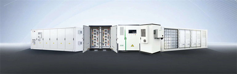
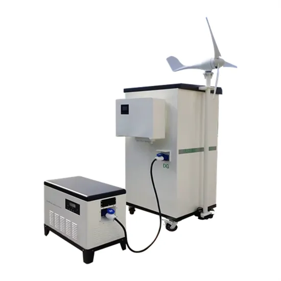
This paper presents the design considerations and optimization of an energy management system (EMS) tailored for telecommunication base stations (BS) powered by. . Looking for advanced BESS systems or photovoltaic foldable container solutions? Download Wireless solar container communication station EMS Grounding [PDF]Download PDF Our BESS energy storage systems and photovoltaic foldable container solutions are engineered for reliability, safety, and efficient. . Do I need a DC grounding system for a stationary off-grid system? In a stationary off-grid system, a separate DC grounding system should be used for the charger, batteries, and inverter input, independent of the household AC grounding system, to avoid interference. The EMS serves as the central intelligence hub, orchestrating the operation of batteries, inverters monitoring devices, and other subsystems vironmental monitoring in the container,com atible with the 2h system. .
[PDF Version]