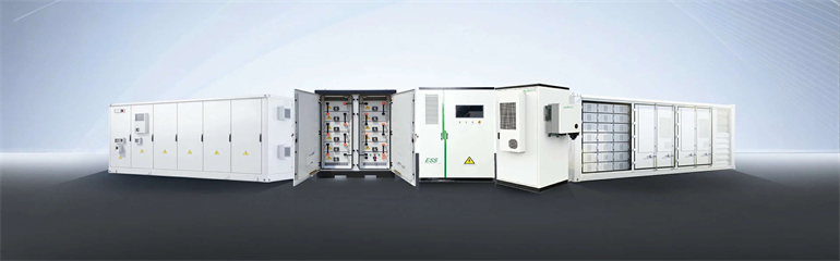
NEC Article 690 covers the installation and safety requirements for solar photovoltaic (PV) systems. It defines the components like arrays, modules, inverters, and disconnecting means, and outlines how circuits must be sized, protected, grounded, and labelled. There are standards for nearly every stage of the PV life cycle, including materials and processes used in the production of PV panels, testing methodologies, performance y an important role in the. . Most manufacturers today do business across the globe and have their PV modules evaluated to multiple safety standards which is costly and in some cases results in duplication of effort. and international safety standards, opportunities to harmonize IEC and UL. . ic criteria to promote sanitation and protection of public health and the environment. Provisions for mechanical and electrical safety have not been included in this Standard because governmental rovided, are intended to assist in understanding their adjacent standard requirements.
[PDF Version]
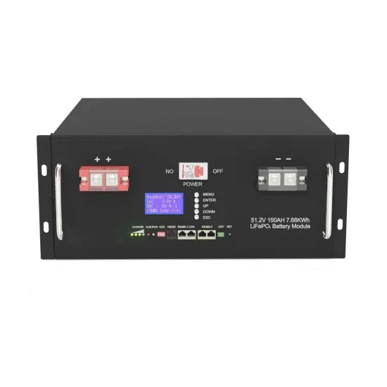
Modules included in this chart of the current state of the art have efficiencies that are confirmed by independent, recognized test labs—e., NLR, AIST, JRC-ESTI and Fraunhofer-ISE—and are reported on a standardized basis. . This report presents a performance analysis of 75 solar photovoltaic (PV) systems installed at federal sites, conducted by the Federal Energy Management Program (FEMP) with support from National Renewable Energy Laboratory and Lawrence Berkeley National Laboratory. Learn how NLR can help your team with certified efficiency measurements. National Renewable Energy Laboratory, Sandia National Laboratory, SunSpec Alliance, and the SunShot National Laboratory Multiyear Partnership (SuNLaMP) PV O&M Best Practices. . Since solar PV power installations are generally set up for a period of 25 years and solar PV cells and modules used in plants require long term warranty, it is desirable to ensure that such products are indeed made in units in which production has been claimed. It is possible that some units may. . Learn about PV module standards, ratings, and test conditions, which are essential for understanding the quality and performance of photovoltaic systems. Basic Understanding of Solar Cell Structure and Function 1.
[PDF Version]
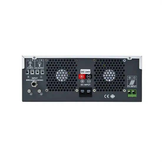
Required grounding equipment includes copper-clad ground rods (5/8 inch or 3/4 inch diameter, 8-10 foot length), grounding clamps, UL2703 certified bonding products, and listed terminal bars. Ground rod spacing requires minimum 6 feet separation between electrodes. . Many modern grid-tied installations use ungrounded PV arrays paired with transformerless (non-isolated) inverters that establish a functional ground reference and rely on electronic ground-fault detection. Solidly grounded PV source circuits remain a permitted configuration and are still used in. . If separate grounding systems and grounding electrode conductors (GECs) are installed in a structure or different buildings, they should be combined at a common point (busbar or terminal) and connected to the common grounding electrode system. The main bonding jumper (MBJ) and grounding electrode. . Solar PV grounding systems require specific equipment to meet National Electrical Code (NEC) safety standards under sections 690. This simple yet critical detail can save you time, money, and headaches down the road. Whether you're a DIY enthusiast or just want to understand the process better, this. . The NEC is the primary guiding document for the safe designing and installation practices of solar PV systems in the residential and commercial markets in the United States.
[PDF Version]
The recommended torque for mounting bolts typically ranges from 20-25 ft-lbs (27-34 Nm), though specific values may vary by manufacturer and local building codes. Always use stainless steel hardware rated for outdoor use, including lag bolts (minimum 5/16″ diameter), washers, and. . When securing photovoltaic (PV) bolts during the installation of solar panels, applying the correct torque is critical to ensure a secure mount without causing damage to the bolts or the mounting structure. After analyzing 37,000 installation records from SolarTech's database, we've identified three critical torque specification tiers: For racking. . lock nuts,the K value can vary between 0. Use Prevailing Tor nnect and secure various equipment and structures. In photovoltaic systems, a variety of different types of fasteners can be employed de ending on their function and application scenario. Proper torque is essential to ensure that everything stays in place and functions correctly. When installing multiple rows, maintain a minimum gap of 1 inch between panels to allow for thermal expansion and facilitate maintenance access. The ET installation manual recommends the clamp bolt should be torqued to 8-10 Nm (6-7. I would like to use the higher value to insure. .
[PDF Version]
The Federal Energy Management Program (FEMP) provides this tool to federal agencies seeking to procure solar photovoltaic (PV) systems with a customizable set of technical specifications. Select the plus sign in the rows below for more. Since PV is such a global industryit is critical that PV products be measured and qualified the same way everywhere in the world. IEC TC82 has developed and published a number of module and component measurement. . Solar mounting systems comprise several components: Mounting Brackets:These secure the solar panels to the mounting structure,ensuring stability. If the existing products are not suitable for your needs,we can also eeland aluminum alloy extrusion profile AL6005-T5. But here's the thing – these standards aren't just bureaucratic red tape. Let's break down the numbers: Wait, no –. . Therefore, it is essential to understand different mounting types for the efficient installation, maintenance, and durability of solar modules and other components. What are mounting brackets &. .
[PDF Version]
The typical thickness for these rigid, framed modules falls within a narrow range of 30 millimeters to 40 millimeters, translating to approximately 1. A common measurement found across many modern manufacturers is 35 millimeters, which balances structural integrity with material. . How thick should a solar panel be to maximize energy production while ensuring durability? This article explores the critical role of photovoltaic cell module thickness specifications in solar technology. The amount of light absorbed depends on the optical path length and the absorption coefficient. The animation below shows the. . The silicon wafer size has undergone three major changes: the first stage from 1981 to 2012, the silicon wafer size is mainly 100mm, 125mm; The second stage from 2012 to 2015, mainly 156mm (M0), 156. 75mm (M2); Since 2018, large size silicon wafers such as 158. 7mm (M4), 166mm (M6). . Photovoltaic (PV) systems (or PV systems) convert sunlight into electricity using semiconductor materials. If you're buying solar panels from overseas, knowing about thickness can save you headaches and money.
[PDF Version]