To calculate the series resistance (Rs) for a solar cell, specific methodologies and formulas must be employed. Understand the IV curve, 3. Apply the Schottky diode equation. Additionally, the temper-ature of the sol r cell should be kept. . This study introduces a research proposal aimed at analyzing the losses associated with series resistance (Rs). The solar panel voltage calculator determines the voltage at outputs of solar panels that are in series or parallel.
[PDF Version]
Solar panels are graded into categories A, B, C, and D based on their quality, and the cost differences between these grades can be significant. Grade A panels, for instance, are the highest quality, while Grade D panels are typically considered low-grade materials with limited. . Learn how solar panels are graded (A, B, C, D), their applications, and why quality matters. Get insights to make informed decisions for your solar project. The cost gap is also very large. So what kind of solar panel is called A grade, and what kind of solar panel is called D grade? Here is a brief. . Photovoltaic panels are devices that convert solar energy into usable electrical energy. When you want to purchase a photovoltaic panel, it's important to understand the basic information present on its nameplate. This nameplate data provides crucial information about the panel's performance and. . Terms like Grade A, B, and C are often used in the industry — but what do they actually mean? And how do they impact the performance, reliability, and return on your investment? At Sova Solar, where we've been manufacturing high-efficiency panels since 2008, we believe it's time to shed light on. . How are grade (A, B, C, D) cells classified? There's a lot of confusion between different grade solar cells. Grade A ave some visual defects that do not affect performance.
[PDF Version]
In the early 1950s, engineers began experimenting with porous carbon electrodes in the design of capacitors, from the design of and . is an that is an extremely porous "spongy" form of carbon with a high . In 1957 H. Becker developed a "Low voltage electrolytic capacitor with porous carbon electrodes". He believed tha.
[PDF Version]
To ensure safe and accurate resistance measurements, always turn off the power, discharge capacitors, and isolate the device being measured from the circuit. These steps prevent electrical hazards and ensure accurate readings. Thus, the answer is 'All of these choices. '. A digital ohmmeter measures resistance by putting a known (constant) current through the resistor, and measuring the resulting voltage to display the resistance using Ohm's law. Why a Circuit Should Be Powered Off When Measuring Resistance with a Digital Multimeter. ' When measuring resistance. . Turn digital multimeter dial to resistance, or ohms, which often shares a spot on the dial with one or more other test/measurement modes (continuity, capacitance or diode; see illustration below).
[PDF Version]
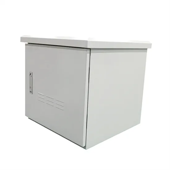
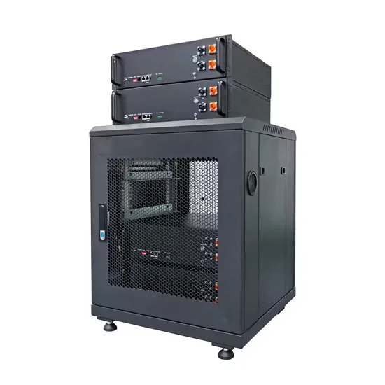
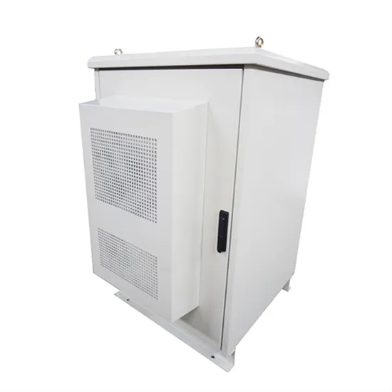
The pre-charging resistance limits the initial charging current, ensuring a gradual and controlled charging process. This component, often overlooked, is crucial in mitigating voltage spikes, minimizing stress on components, and optimizing system performance. This component quietly prevents catastrophic failures when connecting battery banks to inverters, acting like a diplomatic negotiator between overeager electrons and. . Therefore, when we closed the contactors on the battery pack we do this in three steps: A simplified schematic shows the basic principle. In this guide, we explore why battery storage cabinets matter, what makes a good lithium battery. . Precharge resistors play an essential role in high-voltage electronic systems by preventing damaging inrush currents when power is applied. These components significantly extend system lifespan and protect sensitive electronics from premature failure. Failure to manage inrush c rrent can lead to damaged cables,connectors,or fuses. This process protects the. .
[PDF Version]
The NFPA and IEEE recommend a ground resistance value of 5 ohms or less while the NEC has stated to “Make sure that system impedance to ground is less than 5 ohms specified in NEC 50. In facilities with sensitive equipment it should be 5ohms or less”. Ideally, a ground should be zero ohms of resistance, but. . The grounding electrode system must achieve a maximum resistance of 10 ohms, though local regulations may specify stricter requirements. Installation of surge protection devices (SPDs) is mandatory to protect against lightning strikes and voltage surges. DISTRIBUTION LINE FAULTS AND GROUNDINGC BIV. CONSIDERATIONS FOR PV. . The focus of the guide is on differences in practices from substation grounding as provided in IEEE Std 80.
[PDF Version]